To properly use the relay, when the relay is selected and its characteristics are learnt, the precautions for using are required to be known and ensure the reliable operation of the relay.
The following precautions will be considered in application:
1) The relays are used within the range of the parameters listed in the catalogue, to the extent that it is possible.
2) The rated load and the life are the referent values, which will be different due to the different environments, load features and types. Therefore they should be tested in the practical or stimulated application.
3) DC relays are controlled by rectangle wave to the extent that it is possible while the AC relays are controlled by sine wave.
4) To maintain the performances of relays, please do not make the relay drop or be shocked strongly. Suggest that the relays dropped not be used.
5) Relays are used in the ambient temperature and normal humidity and in the atmosphere with less dust and harmful gas. The harmful gases include gases with sulfur, silicon and nitrogen oxide, etc.
6) For the latching relays, please set them in the operate or reset state before they are used. Please pay attention to polarity and pulse width when energizing on the coil
7) For polarized relay, please notify the polarity(+,-) of the coil voltage.
8) Except for the above there are other precautions. In the following they will be described one by one in the order listed in table 2.
Contacts are the most important elements of relay construction. Contact life is influenced by contact material, voltage and current value applied to the contacts (especially the voltage and current waveforms at the time of application and release), the type of load, switching frequency, ambient atmosphere, form of contact and thecontact bouncing etc. The material transfer, welding, abnormal usage and the increase in contact resistance bring about the failure of the contacts. Please pay attention to them in application.
In order to better apply the relay for sale, please refer to the following precautions of the contacts.
1.1 The Load
The resistive load value is usually listed in the catalogue, however, which is not enough. It should be checked and tested in the practical contact circuit.
The minimum load described in the instructions is not the standard lower limit value the relay can switch reliably.
The reliability of this load value is different due to differences of the ON-OFF frequency, the environment, the change of the required CR and absolute values.
1.1.1 Voltage
When the inductive circuit is switched off, there are the reverse voltage which is higher than the electrical circuit.
The higher this voltage is the more the energy is. Correspondently the contact wear and material transfer also increase. Therefore notify the load type and load value the contacts of the relay control.
In the same current, DC voltage value the relay can switch reliably is much less than AC voltage value for AC current exists zero point(the point when the current is zero) and the electrical arc produced easily extinguishes.
However for DC current, the electrical arc extinguishes when the contact gap is up to the certain value. Therefore the duration of the arc is longer than that in AC current and the contact wear and material transfer increases.
1.1.2 Current
When the contacts are on or off, the inrush currents will greatly influence the contacts. For example, when the load is motor load or lamp load, the higher the inrush current when the contact is on, the more the contact wear and the material transfer increase, and the more easily lead to the contact weld and not to separate.
Please check in practical application.
1.2 Precautions For The Application
1.2.1 Avoiding Switching Both The Large Load And The Micro Load In The Same Relay
When switching the high load, the scattered contact material is produced, which will attach to the contacts with the low load and lead to the failure of the contacts. Therefore, please avoid the same relay switching both the high load and the low load. If it is the only choice to do against this, when mounting please place the contacts switching the little load over the contacts switching the large load. However the reliability will be influenced.
1.2.2 Precautions For The Two Pairs Of Contacts Connected In Parallel
When the two poles of contacts are connected in parallel, the reliability will be improved but the load capacity could not, for the two poles of contacts could not be opened or closed at the same time.
1.2.3 The Problems About Phase Synchronism Of contact Operation And AC Load
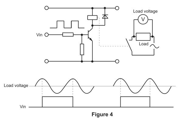
If the operation of the relay contacts is synchronized with the phase of the AC power and the contacts always make or break in the high load voltage, seen in figure 4, the contact weld or material transfer will increase to lead the relay to prematurely fail. Please check whether the random phase are used in actual application. When the relay is driven by timer, micro computer, etc., it will appear the power phase synchronism.
1.2.4 Electrical Endurance In The High Temperature
Electrical endurance of the relay will be lower in the high temperature than that in the low temperature. Please check while it is operating in the actual application.
1.2.5 Connection Of Multiple Pairs Of Contacts And The Load
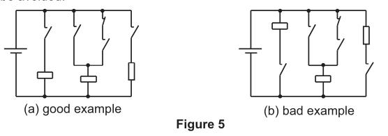
Multi-contacts are arranged in the same polarity of the supply power to the extent that it is possible and the passive polarity in the other polarity of the supply power, as shown in figure 5(a). Thus, the short circuits between the contacts, due to voltage differences between the contacts, can be possibly avoided. The wiring as shown in figure 5(b) can be avoided.
1.2.6 Avoid Short Circuit Caused By Contacts Weld And Electrical Arc
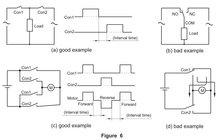
In the electrical circuit, the following points should be considered (seen in the figure 6)
1) Generally the gap between the contacts are small. The reason can probably be that the electrical arc between the contacts results in the short circuit. Please do not adopt the circuit shown in figure 6(b). The circuit shown in figure 6(a) is suggested to use and the certain interval can be set in the operation between Con1 and Con2.
2) It should be considered that the overcurrent should not be generated to make the circuit overload or burn when short circuit is caused by contact welding and error operation.
3) Care should be taken that the two pairs of switching contacts are not used to build the forward circuit and the reverse circuit, as shown in figure 6(d). Suggest that the circuit shown in Figure in 6(c) is applied and the certain interval is set in the operation between Con1 and Con2.
1.2.7 Avoid Short Circuit Between Contacts
The miniaturization of the electrical control equipments makes the control components tend to miniaturization, so the relay with multiple poles of contacts are used, care is taken of the differences of the voltage between the poles of contacts and load types. Suggest that large differences of the voltage among the contacts do not exist in order to avoid short circuit between poles of contacts.
1.2.8 Precautions For Using The Long Lead Wire
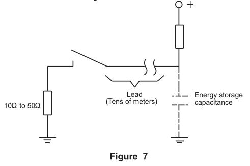
In the contact circuit of the relay, when the lead wire with more than 10m length is used, the inrush current will be generated due to the capacitance in the lead wire. Please connect in series the resistance(about 10 to 50) in the contact circuit, as shown in Figure 7.
1.2.9 Precautions for the contacts of the magnetic latching relays
Generally the latching relays are shipped from the factory in the reset states. However during shipping or mounting relays the shock of the relay may change the operate state. Therefore suggest that in application it be set in the required state.
1.3 Contact Protection
1.3.1 Inrush Current And The Reverse Voltage
When the motor, capacitance, solenoid and lamp load make, the inrush current is generated, which is several multiple steady state currents.
When the inductive load such as solenoid, the motor, contactor, the reverse voltage which are from hundreds of to thousands of volts. Generally in the normal temperature and atmospheric pressure the critical insulation destruction voltage of the air is 200 to 300V. Therefore if the reverse voltage exceeds this value, the discharge phenomena between contacts will happen.
Both inrush current and the reverse voltage will greatly damage the contacts and obviously shorten the relay life.
Therefore the proper use of the contact protection circuit may increase the life of the relay.
1.3.2 Material Transfer Of Contacts
Material transfer of contacts refers to the transfer of the contact material from one contact to the other. When material transfer becomes serious, the accidented contact surface can be seen by eyes. As shown in figure 8, the accidented surface easily causes contact welding.
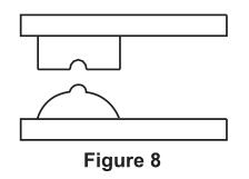
Generally, material transfer of contacts is caused by the one-way flowing of the large current or the inrush current of the capacitive load and often happens in DC circuit. Generally it shows the protruding shape in the passive polarity and the concave shape in the positive polarity. Therefore the proper use of the contact protection circuitor the use of AgSnO contact which has better resistance against material transfer may reduce the material transfer of contacts. The AC load with large capacity should be checked in actual application in the test.
1.3.3 The Protective Circuit Of The Contacts
Generally speaking, in contrast to resistive load, inductive load more easily damages the contacts. The use of properly protective circuit may make the influence of inductive load on the contacts equal to the influence of resistive load on the contacts. Care is taken that the incorrect use will generate the counter effect. Table 11 shows the typical examples of the contact protective circuit.
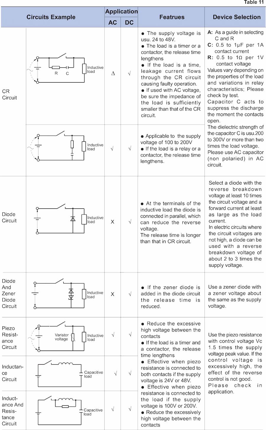
Notes: the mark "√" means good, the mark "X" means bad, the mark means notice. Please avoid using the following circuit as table 12.

1.3.4 Precaution For mounting Protective Elements
When the protective elements such as diode, C-R, piezo resistance are mounted, they must be mounted beside the load or the contacts. If the distance is far, the protective effect will not be good. Suggest to be mounted within 50cm.
The application of rated voltage to the coil is the basis for a relay to work normally. Only applied the voltage beyond the operate voltage, the relay can work, but the rated voltage must be applied to the coil for the changes caused by the temperature and the variation of the power voltage will influence the normal operation of the relay.
2.1 Types
2.1.1 AC Operation Type(AC type)
Generally the work voltage of the relay is always a commercial frequency (50Hz or 60Hz). Suggest that the products with standard voltage specifications listed in the instructions be selected to the extent that it is possible.
If the products with other specifications are required, Please contact the technicians in HONGFA company. For AC relays, due to the factors such as eddy current loss, hysteresis loss and lower coil efficiency, the temperature rise is greater than that for DC type. When voltage exceeds ±10% of rated voltage, the buzz is easily produced. Please notify the variation of the power voltage.
For AC relays, when the coil breaks, there should not remain any DC voltage in the circuit; otherwise, the relays can not release normally.
2.1.2 DC Operation Type(DC type)
Generally, the DC relays mostly are voltage drive type. Suggest that to the extent that it is impossible, the products with the standard voltages listed in the instructions should be selected. If the products with other specifications are required, Please contact the technicians.
Please check the voltage polarities of the relay coils in the instructions. If the diode for the control or the elements for displaying are added, once the opposite connection of the voltage will lead to the abnormal operation of the relays or the abnormal operation of the added elements or even short circuit. When the coil is parrelled with diode or LED, the release time will be prolonged which may reduce the electrical endurance. Please note that.
In addition, for polarized relay, the polarity of the voltage applied to the coil is opposite to that in the instruction, the relay will not work.
2.2 Input Power Of The Coil
2.2.1 Input Power For AC Coil
To make the relay work reliably, please apply rated voltage to the coil. If the voltage, which does not make the relay completely operate, is continuously applied to the coil, the coil will abnormally heat to make the coil abnormal wear.
The supply voltage of AC relay would better be sine curve. The AC coil can better control the buzz. If the waveform distorts or deforms, the control function can not be displayed better. Figure 9 shows several examples of common waveforms.

If the parts such as the motor, solenoid and transformer are connected in the drive circuit of the relay, when the parts work the coil voltage of the relay will reduce and then the relay contacts will shake to cause the contact welding, abnormal wear or non-conduction. The alike phenomenon of the reduction of the coil voltage will happen when the miniature transformer are used, no transformer with rich capacity can be used as the power source and the wiring is long, the wiring used in the house or the shop, etc. is thin. If the similar failure happens, Please use the synchro oscilloscope to check and properly adjust.
If using the loads with large variation such as the motor, Please separate the drive circuit of the coil from the power circuit according to the usage.
If the AC relay could not work reliably, switch AC to DC and then select the proper DC relay.
2.2.2 Input Power For DC Coil
In order to work steadily, the voltage applied to the two terminals of the coil of the DC relay is suggested to use
the coil rated voltage under ±5% or the relay could not work steadily, to cause the contact welding or abnormal wear, especially when such parts as the motor, solenoid or transformer, etc. are connected in the drive circuit of the relay, the case will be more obvious As the power source of DC relay, there are the accumulator, the full(as shown in 10) or half wave rectifier circuit of smoothing capacitor, which will influence the operating characteristics of the relays. Please check in the practical application.

2.3 Maximum Voltage Of The Coil
Except for the limits from the coil temperature rise and the heat-resistant temperature of insulation material of the coil electro-magnetic wire(once beyond the heat-resistant temperature, short circuit will locally happen in the coil and even the coil burns), the maximum voltage of the coil will be influenced by heat distortion and the aging of the insulation materials. Especially it can not destroy other machines, hurt the human body or cause the fire, so it must be limited with the certain range. Therefore please do not make it beyond the regulated value in the instructions.
Maximum voltage is the maximum value of the voltage which can be applied to the coil of the relay in short time rather than the value of the voltage allowed to be continuously applied with.
2.4 The Coil Temperature Rise
2.4.1 Temperature Rise
In the course of the relay operation, the coil temperature will be increased. When a pulse voltage with ON time of less than 2 minutes is used, the coil temperature rise value is related to the ON time and the ratio of ON time to OFF time. The various relays are essentially the same in this aspect. (table 13)

2.4.2 Pick-up Voltage Change Due To Coil Temperature Rise
The temperature rise causes the increase of the coil resistance and correspondently the pick-up voltage will increase. the resistance temperature coefficiency of the copper wire is about 0.4% per 1℃. with this ratio, the coil resistance increases. Pick-up, release and reset voltages in the instructions are all the values in 23℃.
When the coil temperature is beyond 23℃, pick-up voltage surpasses sometimes the speculated value in the catalogue. Please check in the practical application.
2.5 Leakage Current
When designing the circuit, please avoid the leakage current flowing through the relay when the relay does not work.

2.6 Energized Voltage Of The Coil And Operation Time
In the case of AC operation, there is extensive variation in operate time according to the difference of the phase when the coil is applied with the voltage.
In the case of the DC operation, although the voltage applied to the coil increases and operate time of the relay will properly become rapid, the contact bounce time when the contacts closes is extended to cause the reduction of the life or the contacts welding when they work in the rated load or in the large inrush current.
2.7 The Application Of The Relays Connected In Parallel And In Series.
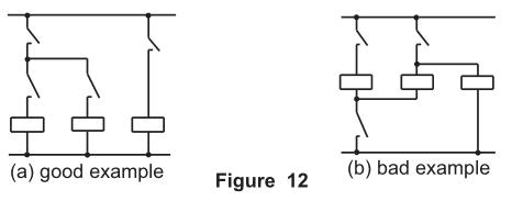
Several relays connected in parallel, please take care of the wrong operation for the bypass current and leakage current shown as figure 12.
2.8 Avoid Gradual Increase Of Coil Impressed Voltage
In the course of the operation, the relay experiences such phases as contact pressure changing, contact bounce and the unstable condition of the contacts. When gradual increase of coil impressed voltage happens, the time of the unstable phase becomes longer to affect the life of the relay.
In order to reduce the influence on the relay, please impress bypass voltage to the coil, to the extent that it is possible.
2.9 Precaution For The Long Power Wire
If the power wire is longer, please select the relay according to the principles of impressing the rated voltage after testing the coil voltage of the relay.
If paralleled with the power line and long distance, when the supply power of the coil is switched, the voltage at the terminals of the coil will be generated due to the capacitance stored in the wire and then result in the release worse. In this case, Please connect the bypass resistor at the two ends of the coil.
2.10 Long Term Current Carrying
If the coil is continuously applied the power to for a long term, the self heating of the coil promotes the aging of the insulation materials of the coil and the worse characteristics, so in this case please use the latching relay. If the monostable relay must be used, please use the hermetic relay which is not easily influenced by the external environments and also use the suitably protective circuit to prevent the loss due to the contact failure or the break of the coil wire.
2.11 Low ON-OFF Frequency
When the ON-OFF frequency is below once per month, please periodically check the states of the contacts. If the contacts keep the non ON-OFF state for a long time, the organic film will be formed on the surface of the contacts and result in the contact failure.
2.12 Electrolytic Corrosion Of Coils
When the relays are placed in high temperature and high humidity atmospheres or with continuous passage of current, that the coil is grounded will make the coil electrolytic errosion to cause the break of the electro-magnetic wires. Therefore please do not make the coil grounded to the extent that it is possible. In the case where unavoidably the coil is grounded, please set the control switch of the relay coil in the positive side of the coil.
2.13 Precaution For The Coil Of The Magnetic Latching Relays
2.13.1 The Coil Voltage
Please check whether the direction of coil impressed voltage is correct or not, or the relay may not work.
Due to the characteristics of the magnetic latching relays, to prevent the relay against overheating and then burning. the long-term impressed voltage on the coil are not allowable.
2.13.2 Self-locking Of The Relays
Please avoid using the NC contacts of the relay itself to switch off its own coil. Otherwise, the failure will happen.
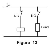
2.13.3 Precautions For Using The Relays Connected In Parallel
When the coil of the latching relay is connected in parallel with the coil and the solenoid of other relays, please add diode to prevent the reverse voltage from influencing the normal work of the relay.
2.13.4 Width Of Minimum Impulse In Operating And Resetting
In order to make the latching relay operate or reset, please impress the rectangle rated voltage for more than 5 times at the operate time or the reset time on the coil and then operate it. If the impulse width can not meet the requirements above, please check in the actual application.
Please avoid using in the conditions that the power source has many surges.
2.13.5 Precautions For The Double-Coil Relay
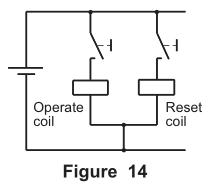
Do not impress the voltage on the set coil and reset coil at the same time, or the relay will abnormally heat, abnormally operate and even abnormally wear.
As shown in figure 14, when the terminals of either of operate coil and reset coil in the circuit are required to connect and the other terminals are connected to the same polarity of the power source, Please directly connect the terminals to connect(short circuit) and then connect to the power source. Thus the insulation between the coils can be maintained well.
2.13.6 The Drive Circuit Of The Latching Single-Coil Relay
As shown in figure 15, it is one of the drive circuits of the latching single-coil relay. When the signals are input, the current charges the capacitance C and in turn charges the coil and then make the relay operate; when the signals are removed, the electric power stored in the capacitance C will discharge through trinode Tr and the coil and make the relay reset.

3.1 Precautions For Plastic Sealed Relays
Hermetic relays can resist under bad surroundings. However, please pay attention to the following precautions in application to avoid the failure.
3.1.1. Regarding Practical Environment
Plastic sealed relays are not suitable for using in the environment which has the special requirement for the air seal. Please avoid using them in the pressure exceeding 86kPa to 106kPa.
3.1.2. Regarding washing
When washing PC board after the terminals soldered on PC board, suggest that the washing can be done by washing solvent of alcohol series.
Please avoid supersonic washing for supersonic washing may cause the break of the coil wire and the light contact welding.
3.2 Vibration And Shock
The transient break of the contacts when the relays are shocked strongly, will lead to the false operation.
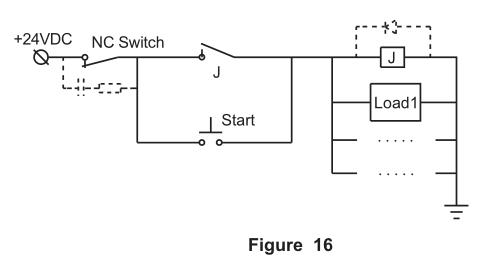
Therefore, when the relays are mounted on the same board with other parts(such as electromagnetic switch, air switch et.) which can produce the shock, the measures of reducing the influence of the shock on the relay should be taken. For example, make the direction of the shock and direction of relay contacts make/break at the right angles to the moving direction of armature, or to mount these components on different boards, or using a buffer tablet, or to take some measures in the application circuit to reduce the impact of false operation of relay contacts(as illustrated by figure 16):
Remarks:
in the above figure, a RC is parallel connected to NC switch, and a FWD is parallel connected to relay coil. This measure can avoid the abnormal cut-off of the circuit caused by the abrupt break of NC switch under strong shock and vibration.
In addition, for the relay in the vibration atmosphere in the long term(such as electrical car), please avoid combining with the socked in application. Suggest that the relay be directly soldered on the PC board.
3.3 The Influence Of External Magnetic Fields
If there is the strong magnetic fields around the relay, if the relay is mounted beside the large relay, transformer or the speaker, the characteristics will produce the false operation with the variation of the external magnetic fields, especially for polarized relays. Because the operation of the relay is dependent on the internal permanent magnet, it is easily influenced by the external magnetic fields. Please pay attention to the mounting position in practical application and check.
3.4 Vibration, Shock And Weight During Shipping
During shipping the relay or the equipment with the relay installed, the large vibration, shock and weight will cause the failure of the relay functions. Please use the cushion package to control the vibration and shock within the allowable range.
4.1 Regarding Ambient Temperature And Atmosphere
Care is taken that the ambient temperature at the installation does not exceed the value listed in the instructions.
In addition, the contact surface will form sulfured film, oxide film or attached dust in an atmosphere with dust, moisture and sulfur gases(SO2, H2S, etc.) or organic gases to cause the unstable contact and the failure of the contacts. Therefore please select sealed relays. If the plastic sealed relay is selected, it is required to check in application.
4.2 The Harmful Gases To The Relay
Please do not use the relay in the atmosphere with the following gases. In these atmospheres, plastic sealed relays can not avoid the influence of gases on the contacts. Please use the hermetic relays.
4.2.1 Silicon Atmosphere
Silicon-based substances(silicon rubber, silicon oil, silicon-based coating material and silicon caulking compound, etc.) around the relay will emit volatile silicon gas, which may cause the silicon to adhere to the contacts and may result in contact failure.
4.2.2 Sulfureted Gas
Sulfured gases easily sulfur the contacts and result in the contact failure or non-conduction.
4.2.3 NOx Gas
When a relay is used in an atmosphere high in humidity to switch a load which easily produces an arc, the NOx created by the arc and the water absorbed from outside the relay combine to produce nitric acid. This corrodes the internal metal parts and adversely affects operation. Please do not use the relay in the atmosphere where the humidity is beyond 85% RH(at 20℃).
4.3 The Circumstance With Water, Leechdom, Solvent And Oil
Do not use and store the relays in the atmosphere where the relays may be attached to by water, leechdom, solvent and oil, etc. for water and leechdom may make the parts rusted, the plastics aging and also result in leakage current which damages the relays or the circuit and solvent and oil may make the marks disappearing or the parts aging. For covers made from PC materials, please prevent from contamination by some organic solvents; otherwise it is likely to lead to bulging or crack.
4.4 Atmosphere Of Usage, Storage And Transport
During usage, storage and transportation, avoid locations subject to direct sunlight and maintain normal temperature, humidity and pressure conditions. The allowable range of the temperature and humidity suitable for usage, storage and transportation are shown in the unshaded part in figure 17. The allowable temperature may differ with the types of the relays. In case that the condition in real application is different from that of IEC 61810-1, UL508, UL60947-4-1, GB/T21711.1, etc. the electrical endurance of the relay must be confirmed by tests.
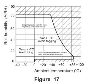
The suggested ranges of the temperature and humidity during usage, transportation and storage are as follows.
1) temperature: 0°C to 40℃
2) humidity: 5% RH to 85% RH
3) air pressure: 86kPa to 106kPa.
4.4.1 The Atmosphere High In Humidity
In the atmosphere high in humidity, when the temperature around sharply changes, the dew will be formed in the internal of the relay and result in the cracking of the insulation material, the break of the coil wire and the rust. The typical examples will happen on the ship transporting on the sea.
Dewing is a phenomena that the vapor freezes water drops in the atmosphere high in temperature when the temperature sharply reduces from the high temperature to the low temperature or the relay is moved in the high temperature from the low temperature.
4.4.2 Low Temperature(under 0°C) Environment
Please note the icing phenomena in the environment with low temperature(under 0°C). Icing may result in the welding of the movable parts, the delay of the operation or preventing the operation, etc.
lcing refer to the phenomenon that water attached to the relay will freeze ice when the temperature reducing below freezing point.
4.4.3 Low Temperature, Low Humidity Environment
Note that the plastics may embrittle in low temperature, low humidity environment.
4.4.4 High Temperature, High Humidity Environment
Note that if the relay is in high temperature, high humidity environment for a long time the contact surface easily forms the oxidized film and then results in the unstable contact and the failure of the contacts. Other metal parts also are easily oxidized or rusted to result in the failure of the functions.
4.4.5 SMT Environment
The relay of SMT type is sensitive to the humidity so they are packed with humidity proof package. The following points should be considered during storage.
1) Please use the humidity proof packing bags as soon as possible after they are unsealed.
2) If the humidity proof packing bags need long term storage after they are unsealed, it is suggested that the desiccator with humidity control be used to store them.
5.1 Top View And Bottom View
Generally the bottom view is the projection whose projection plane is terminal side. Otherwise, the top view is the projection whose projection plane is cover side. Please take care of it when using the instructions or mounting the relays.
5.2 Mounting Direction
Unless otherwise stated, mounting direction of the relays is arbitrary. In order that the relay can work more stable and reliable, mounting direction need cosidering.
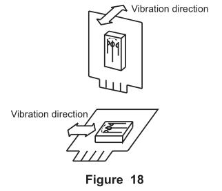
5.2.1 Vibration Resistance And Shock Resistance
It is ideal to mount the relay so that the movement of the contacts and movable parts is perpendicular to the direction of vibration or shock. Especially when the coil is not excited, the vibration or shock resistance of NC contacts is weak. If mounting direction is proper, their functions can be ensured. (figure 18)
5.2.2 Contact Reliability
Mounting the relay so the surfaces of its contacts are vertical prevents dirt and dust as well as scattered contact material and powdered metal from adhering to them when the arc is generated.
5.3 Adjacent Mounting
When many relays are mounted close together, abnormally high temperatures may result from the combined heat generated. To prevent the heat buildup, please mount relays with sufficient spacing between them.
When many boards mounted with relays are installed in a card rack, please be sure that the ambient temperature of the relay does not exceed the value listed in the instructions.
5.4 Shroud Mounting
Use the gaskets when mounting to prevent from the damages and deforms. Keep the screwing moment in the range of 0.49 to 0.686N·m(5 to 7kgf· cm. To prevent from loosening, please use the spring gasket.
5.5 Mounting The Plug-In Terminals
When mounting the relay with plug-in terminals, the plug-in strength is based on 40N to 70N(4kgf to 7kgf).
5.6 Supersonic Cleaning
Do not clean the relay by the way supersonic cleaning, for the supersonic will result in the contact welding and the break of the coil wire.
5.7 Mounting And Soldering Of THT Relays
The mounting and soldering of the THT relay can be divided into the following steps. (figure 19)
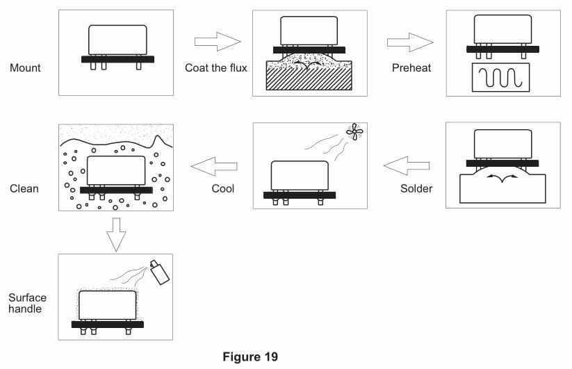
In the following the considered points are described when THT relay is soldered on the PC board. Please refer to them in application.
Note that if the solder entered the relay due to the carelessness, the functions of relay will be destroyed. There will be such problems as the relay not be suitable for the automatic soldering or cleaning due to the different protective constructions. Please see the details in the constructions and characteristics in 3.1 pattern of encapsulation in Chapter 2.
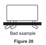
5.7.1 Mounting
Do not bend the terminals of the relay(figure 20) for it may destroy the initial performances of the relay.
Please correctly process the PC board according to the mounting hole drawing in the instructions.
Please maintain the balance of the relay.
Please note that the set force of the hook for mounting is too much large to result in the internal failure of the relay.
5.7.2 Coating Flux
Please use the rosin flux which is not corrosive and the alcohol solvent which is less chemistry.
Please use the thin and even coating flux to prevent from penetrating the relay. As for the dipping coating, please keep the surface of the flux stable.
Please adjust the places to ensure that the flux will not overflow through the surface of PCB.
Please do not make the flux attached to the parts of the relay except for the terminals. Otherwise, the insulation of the relays will be reduced.
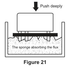
For the dust protected relays and flux proofed relays, do not use the coating method of pushing deeply PCB from the above into the sponge absorbing the flux, as shown in figure 21. This will make the flux penetrating the relay, especially for the dust protective type.
5.7.3 Preheating
In order to improve the soldering performance, please preheat without failure.
Please preheat under 100℃(the soldered surface of the PC board) within 1 minute.
Do not use the relays which are placed in the high temperature for a long time due to the set failure for their initial performance may have changed.
5.7.4 Soldering
Precautions for soldering seen in table 14.

Remarks:
1). The preheating and soldering temperature and time for automatic soldering should be reduced as low as possible to avoid any change in relay performance due to excessively high temperature or too long time preheating or soldering.
2). It is normal if some relay covers become slightly bulging under right soldering conditions.
3). In the process of manual soldering it is prohibited to press or pull the relay terminals because such doing will lead to changes in product performance or even relay failures.
5.7.5 Cooling
After automatic soldering, please ventilate and cool them to avoid the aging of the relay or its parts caused by the heat generated when the relay soldered.
Although the sealed relay can be cleaned, it is not cleaned for the sudden connection with the cool solvent may damage the hermetic characteristics of the relay.
5.7.6 Cleaning
Please select the cleaning method in table 15 when cleaning.

Due to different soldering condition, sealed relays can be impaired when mounting on PCB. If cleaning is necessary after soldering, it is recommended to solder under the condition provided by HF and to select special sealed relays(customer code: 310).
Avoid cleaning with Freon, Trichloroethane, diluent or gasoline.
5.7.7 Surface Handling
In order to prevent the insulation of PCB from worsening, Please note the following precautions when surface handling.
The dust protected type and the flux proofed type result in the failure due to the surface handling agents penetrating the relay. Therefore please do not do the surface handling or mount the relay after surface handling.
Due to the bad influence of the surface handling agents on the relay eg. melting the cover, please select carefully and check and test in application.
Spraying and brushing processes are recommended for surface treatment, and dip-coating is prohibited. Surface treatment agent should best be room-temperature liquid agent, which should be sprayed when the relay is cooled down to room-temperature. The agent can be dried naturally or under constant temperature which should not exceed 60oC. Meanwhile, the drying temperature is not allowed to be decreased when the agent is not completely dried, otherwise the agent could be absorbed into the relay and thus lead to relay failure.
Please contact us when special surface treatments processes are used so that we can provide you a suitable product.
There are the following suggestions on the coat, as shown in table 16.

5.8 Mounting And Soldering Of SMT Relays.
The mounting and soldering of SMT relays have the following steps, as shown in figure 22. In the following the considered points are listed when the SMT relays are soldered on PCB.
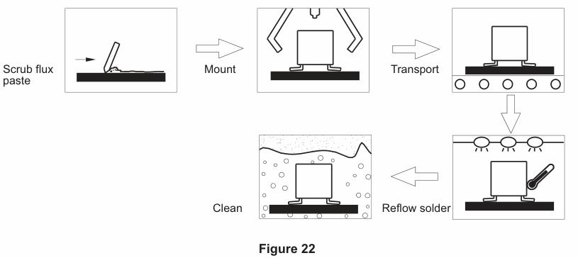
Please refer to these in application. Note that the relays are not damaged in processing.
5.8.1 Scrub Flux Paste
Please use the rosin and chlorin-free flux paste for chlorin may erode the terminals and circuit panel.
Flux paste should be coated evenly and the thickness is 0.15mm or 0.2mm.
5.8.2 Mounting
When mounting the relays, do not set the conservative force of the finger within the range specified in table 17, unless otherwise stated in the catalogue.

5.8.3 Transportation
During the transport, the relays will not fall off due to the factors such as the shock and vibration to avoid the bad soldering produced thereby.
5.8.4 Reflow Solder
Figure 23 shows the temperature curve of the PCB surface when the infrared ray are used to reflow solder.
Please consult the specification of the relays due to the different characteristics of the different relays. If there is no statement in the instructions, Please use the temperature curve as shown in the following figure.
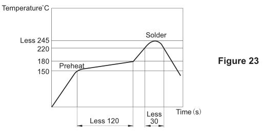
When just finishing soldering, please do not clean the relay immediately, for the connection with the cool solvent may damage the hermetic characteristics of the internal parts.
Do not dip the relay in the flux groove for it will deform the plastics and then result in the failure of the relays.
Please see the soldered state in figure 24.

5.8.5 Cleaning
Hot cleaning or soap cleaning can be used and the cleaning temperature should be controlled under 40℃.
Please use the alcohol solvent or water to clean and do not use Freon, thinner or gasoline to clean.
Do not use supersonic to clean, or the break of the coil wire and the contact welding will be resulted in.
Improper welding will decrease the relay sealing, so please do not clean the relay or do the surface treating(soaking prtector).
6.1 Precautions For The Safety
When the relay works, do not touch the relay with hands for there is the danger of getting the electric shock.
Please switch off the power when mounting, maintaining and handling the relays(including the connecting parts such as terminals and sockets).
When connecting the terminals, firstly refer to the wiring diagram in the instructions, and then make correct connection. The false connection may result in the unexpected false operation, abnormal heating or fire.
If the contact welding, the failure of the contact or the break of the coil wire happens, other properties or lives will be threatened. Please use the double mounting sets.
6.2 Tube Packaging
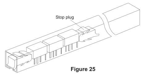
When packing the relay by the tube, do not shake the tube to shock the relays, for which will result in the failure of the relays. If the package uses the stop plug, be sure to slide the stopper plug to hold the remaining relays firmly together so they would not move in the tube.
