Applying rated voltage to the coil is the basis for the normal operation of the relay. When only applying a voltage exceeding the operating voltage, the relay can be tooled, but considering the changes caused by power supply voltage fluctuations and temperature rise, which will affect the normal tooling of the relay, the rated voltage must be applied to the coil.
2.1 Safety type
2.1.1 AC action type (hereinafter referred to as AC type)
Generally, the working voltage of AC type relays is basically 50Hz or 60Hz power frequency voltage. It is recommended to choose products with standard voltage specifications listed in the product manual. If other voltage specifications are required, please contact Hongfa technical staff to confirm .
For AC type relays, due to factors such as eddy current loss, hysteresis loss and reduction of coil efficiency, the temperature rise is generally higher than that of DC type. When the voltage exceeds ±10% of the rated voltage, a buzzing sound is likely to occur, so please pay attention to the fluctuation of the power supply voltage.
For AC-type relays, when the coil is de-energized, there must be no residual DC component voltage in the power supply bribe, otherwise the relay may not be released normally. And the residual AC component voltage is as close as possible to 0VAC, otherwise it may cause the relay to produce a buzzing sound.
2.1 DC working type (hereinafter referred to as DC type)
Generally, DC relays are mostly voltage-driven. It is recommended to choose products with standard voltage specifications as judged in the product manual. If other voltage specifications are required, please contact Jintian technical staff for confirmation.
Please confirm the voltage polarity of each relay coil in the manual. If a suppression diode or a display device is added, once the voltage of the coil is reversed, it will cause the relay to malfunction, or the additional device will operate abnormally, or even lead to a short circuit. Connecting the coil in parallel with diodes or display devices (light-emitting diodes) will cause the relay release time to be longer, which may affect the electrical durability, please be careful.
In addition, for polarized relays, if the polarity of the voltage applied to the coil is opposite to that specified in the manual, the relay will not work.
2.2 Coil input power
2.2.1 AC coil input power
In order to make the relay work stably, please apply the rated voltage to the coil. If a voltage that cannot fully operate the relay is applied (continuously applied) to the coil, the coil will heat up abnormally, causing abnormal loss of the coil.
The power supply voltage of the AC relay is preferably a sine curve, because in the case of a sine wave, the AC coil can better suppress the buzzer, if the waveform is distorted or distorted, this suppression function cannot be very good Play. Figure 9 shows examples of several common waveforms.

If devices such as motors, solenoids, transformers, etc. are connected to the drive circuit of the relay, when these devices work, the voltage on the relay coil will decrease, causing the contacts of the relay to vibrate, resulting in contact bonding, Abnormal loss or failure. When a small transformer is used, or a transformer without sufficient capacity is used as a power source and the wiring is long, or when the wiring is thin for home use, store use, etc., a phenomenon similar to the voltage drop of the coil may also occur. If a similar failure occurs, please use a synchronous oscilloscope to detect and adjust it correctly.
If a load with large fluctuations such as a motor is used, please separate the drive circuit of the coil from the power circuit according to the application.
If the AC relay cannot work stably, the AC can be converted to DC, and then an appropriate DC relay can be selected.
2.2.2 Input power of DC coil
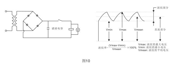
In order to work stably, it is recommended to use a coil rated voltage with a ripple change rate of less than ±5% for the voltage applied across the coil of the DC relay, otherwise the relay will work unstable, causing contact bonding or abnormal loss, especially in the relay This situation is more obvious when devices such as motors, solenoids, and transformers are connected to the drive circuit.
As the power source of the DC relay, there are batteries, full-wave (as shown in Figure 10) or half-wave rectifier circuit with filter capacitor, etc. These different types of power sources will affect the operating characteristics of the relay, so please confirm it in actual use.
2.3 Maximum coil voltage
The maximum voltage of the coil is not only limited by the temperature rise of the coil and the heat-resistant temperature of the insulation material of the coil enameled wire (Once the heat-resistant temperature is exceeded, the coil will be partially short-circuited or even burned out), and it is also subject to thermal deformation of the insulating material, The effects of aging. In particular, it should not damage other machines, endanger human safety or cause fire, so it should be restricted to a certain range. So please do not exceed the value specified in the manual.
The maximum voltage can be applied to the maximum voltage value of the relay coil in a short time, rather than the voltage value that allows continuous application.
2.4 Coil temperature rise
2.4.1 Temperature rise
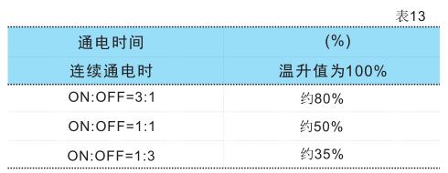
During the operation of the relay, the coil will heat up to increase its temperature. Generally, when the on-time is under 2 minutes of pulse voltage, the temperature rise of the coil is related to the on (ON) time and the ratio of on and off (OFF). Various relays are basically the same, see the table.
2.4.2 Changes in operating voltage caused by coil temperature rise
The temperature rise of the coil will increase the resistance of the coil, and the operating voltage will also increase accordingly. The temperature coefficient of resistance of copper wire increases by about 0.4% per 1°C, and the coil resistance increases by this ratio. The operating voltage, release voltage and reset voltage specified in the product manual are all values at a temperature of 23°C.
When the coil temperature is higher than 23°C, the operating voltage may exceed the specified value in the manual. Please check it in actual use.
2.5 Leakage current
When designing the circuit, please pay attention to avoid leakage current flowing through the coil when the relay is not working, as shown in the figure.

2.6 Coil applied voltage and operating time
AC type relays will have deviations in the operating time depending on the phase when voltage is applied to the coil.
Although the DC relay increases the voltage applied to the coil, the relay's operating time will be appropriately accelerated, but the rebound when the contacts are closed will also increase. Working under rated load or high inrush current will cause the life to be reduced or touch Point bonding, so attention needs to be paid.
2.7 Series and parallel use of several relays
When several relays form a series-parallel circuit, please pay attention to avoid malfunction due to bypass current and leakage current, as shown in the figure.

2.8 The coil should avoid applying incremental voltage
Generally, during the operation of a relay, there are phases such as contact pressure changes, contact jitter, and contact instability. When the voltage applied to the coil is gradually increased, the time of this unstable phase will become longer and affect the relay's performance. Service life. In order to minimize the impact of this situation on the relay, please try to use a step voltage (using a switch circuit) to power the coil.
2.9 Precautions when the power cord is long
If the power cord is long, be sure to select the relay according to the principle of applying the rated voltage after measuring the voltage across the relay coil.
If the long-distance wiring is performed in parallel with the power line, when the coil power is disconnected, the two ends of the coil will generate a voltage due to the parasitic capacitance of the wire, which will cause poor release. In this case, please connect the two ends of the coil next to road resistance.
2.10 Continuous power on for many years
When the coil is continuously energized for a long time, the coil's own heat will cause the aging of the coil's insulation material and the deterioration of its characteristics. Therefore, in this case, please use a magnetic latching relay. If you must use a monostable relay, please use a sealed relay that is not easily affected by the external environment, and use an appropriate protection circuit to prevent loss in case of poor contact or disconnection.
2.11 Small frequency on and off
When the on-off frequency is less than once a month, please check the contact connection regularly. When the contacts are not turned on or off for a long time, an organic film may be formed on the surface of the contacts to cause poor contact.
2.12 Coil galvanic corrosion
When the relay is placed in a high temperature and high humidity environment for a long time or when it is continuously energized, if the coil is grounded, it is likely to be electrolytically corroded and cause disconnection, so please try not to ground the relay coil. If the coil has to be grounded, set the control switch at the coil end of the relay to the positive end of the coil.
2.13 Precautions for magnetic baute relay coil
2.13.1 Coil voltage
Please confirm whether the direction of the voltage applied to the coil is correct, otherwise, the relay may not operate.
Due to the characteristics of magnetic latching relays, it is not allowed to apply voltage to the coil for a long time to prevent the relay from overheating and burning.
2.13.2 Self-locking of relay
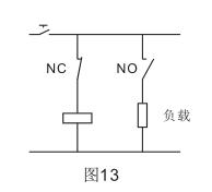
Please avoid using the relay's own normally closed contact to cut off its own coil, as this will cause malfunctions due to the instability of the relay action, as shown in the figure.
2.13.3 Precautions for using several relays in parallel
When the magnetic latching relay coil is connected in parallel with other relay coils or solenoids, please add a diode to prevent the reverse voltage from affecting the normal operation of the relay.
2.13.4 Minimum pulse width during operation and reset
In order to make the magnetic latching relay operate or reset, please apply a rectangular rated voltage to the coil that is more than 5 times the operation or reset time specified in the manual, and then confirm the operation. If the pulse width does not meet the above requirements, please test and confirm in actual use.
Please avoid using it under the condition that the power supply contains more surges.
2.13.5 Precautions for dual-coil relays
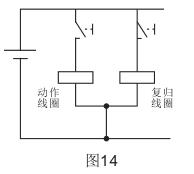
Please do not apply voltage to the setting coil and reset coil at the same time, otherwise it will cause abnormal heating, abnormal operation, or even abnormal loss of the relay.
As shown in Figure 14, when it is necessary to connect either terminal of the action coil and the reset coil on the circuit, and the other terminal is connected to the same pole of the power supply, please connect the two terminals to be connected directly (short-circuit) and then Connect to the power supply, so that the insulation between the two coils can be kept good.
2.13.5 A drive circuit for magnetic latching single coil relay
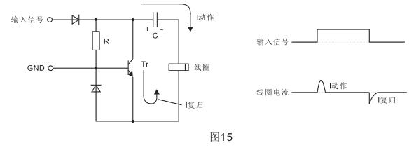
Figure 15 shows a driving circuit of a magnetic latching single-coil relay. When there is an input signal, the current charges the capacitor C, and this charging current is used to supply power to the coil to make the relay operate. When the input signal is removed, the electric energy stored on the capacitor C is discharged through the transistor Tr and the coil Coil to reset the relay.
When using this circuit, please confirm the circuit parameters in actual use.
